El Espino · Electrical planning
How I Would Organize DIN-Rail Junction Boxes at El Espino
External sources open in a new tab so you can keep your place.
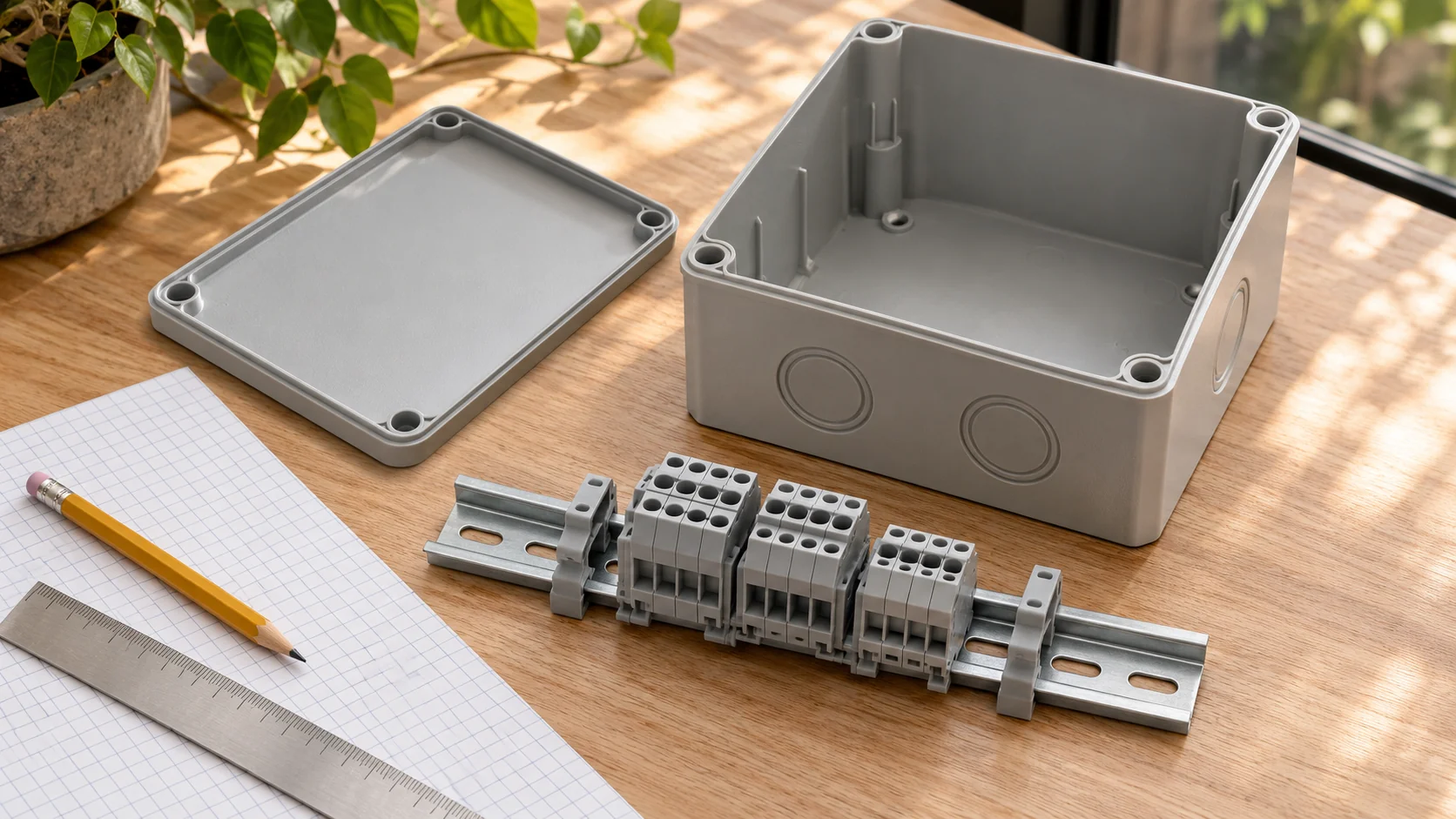
The idea I am examining for El Espino is simple: bring planned conduit runs into accessible junction boxes, organize the connections on DIN rails where the selected system permits it, and label everything so the next person does not need to solve a mystery.
The proposed box size is 8 × 8 × 4 inches. That gives me a starting point for a layout, not a promise that every circuit will fit. This is a proposed layout to examine before installation, with the final enclosure, components, and circuits still to be confirmed.
The attractive part is the organization. A row of identifiable terminals can make a junction easier to understand. The trap is assuming that a tidy row automatically makes a suitable electrical assembly. It takes more than a rail and a lid.
Give every box an address
Before drawing a terminal row, assign the proposed enclosure an identifier, such as JB-A. That is an example label, not an existing El Espino circuit reference. Use that identifier on the route drawing, the enclosure, and its schedule.
Then list each planned circuit entering or leaving it. The record needs the source panel and circuit identifier, destination, conductor information from the electrical design, and terminal references where applicable. Leave unknown information visibly blank rather than fill it with a plausible guess.
That little discipline helps separate “this conduit goes toward the kitchen” from “this documented circuit supplies this particular load.” Both descriptions may be useful, but only one is precise enough for a circuit schedule.
| Record on the schedule | Illustrative entry | What it tells me |
|---|---|---|
| Enclosure | JB-A, proposed | Connects the box to the drawing |
| Incoming route | Route A, source to be confirmed | Identifies the physical conduit |
| Circuit source | Panel and circuit ID from final design | Distinguishes separate supplies |
| Destination | Exact room or equipment label | Avoids vague names like “outside” |
| Terminal reference | X1:01, if adopted in the design | Connects the schedule to the row |
| Conductor details | From approved design, not assumed | Supports sizing and installation checks |
Give the schedule a revision date too. An excellent label describing last month's layout is still the wrong label.
Make a full-size paper layout
An 8 × 8 × 4 label is not a usable interior drawing. CANTEX's 5133712 is a documented example of that nominal PVC junction-box size. I am using it as a size reference, not as a verified DIN-rail enclosure; the rail or backplate mounting method still needs confirmation for the selected box. Its catalog gives separate dimensions and enclosure information. Use the exact chosen box's drawing and mounting provisions to lay out its interior. CANTEX electrical catalog, molded junction boxes, printed page 51
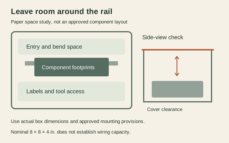
For this proposal, I would start with paper on the bench. Outline the usable interior, the cover's intrusion, proposed entries, and any manufacturer-approved mounting plate. Place paper shapes representing the actual rail and components inside that outline.
The important spaces are often the empty ones: room for bends, entry fittings, conductor slack, terminal access, and the cover. Draw those zones deliberately. Otherwise, it is easy to fit a row of terminals on paper and discover there is nowhere for the conductors to approach them.
Check a side view too. A flat plan hides the height of the rail, blocks, mounting hardware, and wiring. Closing the lid should not be the final stage of a compression experiment.
Terminal dimensions and ratings
Phoenix Contact's PT 2,5, part 3209510, is one example I can use to explain the exercise. It is a feed-through terminal with two connections at one potential. Its published width is 5.2 mm, and its depth on NS 35/7.5 rail is 36.8 mm.
Those dimensions show why the specific part matters. Twelve such blocks occupy 62.4 mm of rail width before end covers, stops, separators, or other accessories. That is only a footprint example, not twelve circuits and not a recommended quantity for this box.
The product page also contains different approval tables. The applicable approval and its conditions govern the actual application. Choosing the largest voltage or current printed anywhere on the page skips that important detail. Phoenix Contact PT 2,5 product data
UL explains that component recognition addresses a component used within a larger product, subject to conditions. It does not certify the complete standalone assembly. That distinction matters here: approved individual parts do not, by themselves, establish approval of my proposed junction box. UL explanation of component recognition
Keep the organization readable
On the layout drawing, group the terminal references by circuit and keep the order consistent with the schedule. Include required end covers, barriers, and end stops in the component list. They are not optional finishing touches. Allow room for labels to remain readable with the wiring installed.
Arrange proposed entries so conductors can reach their assigned groups without unnecessary crossing. If the layout forces everything across everything else, revise the entry plan or compare a larger enclosure. A second suitable box may also be worth comparing. Smaller is not automatically simpler.
Keep separate circuits separate; a neat row of terminals is no reason to bridge them together. Neutral associations must remain as designed; an intentional multiwire arrangement needs its own design. Protective-earth terminals and any rail bonding also require the approved components and conductive path. A gray feed-through block is not a grounding terminal, and a metal rail inside a PVC box does not automatically provide a grounding system.
Three separate checks decide whether it works
Three calculations need their own answers in the design review:
- Raceway fill: whether the specified conductors are permitted in each selected conduit.
- Enclosure suitability: the applicable box-fill or pull-space requirements, terminal space, bends, access, and component installation conditions.
- Conductor ampacity: the effects of multiple current-carrying conductors, temperature, and the actual installation arrangement.
Passing one check does not answer the other two. Multiplying 8 × 8 × 4 produces 256 cubic inches as arithmetic, but it does not establish approved usable wiring volume or a circuit capacity. A claim like “fits six circuits” needs the actual design and equipment information behind it.
This proposal is about organizing junctions. Adding DIN-mounted protection devices brings another set of requirements. Phoenix Contact distinguishes UL 1077 supplementary protectors from UL 489 branch-circuit protection; the word “breaker” on a compact device is not enough to make it a replacement for the required branch protection. Phoenix Contact power-reliability brochure
The finished arrangement must remain serviceable
For El Espino, the actual exposure comes first when selecting the enclosure and entries. A rating on an empty box does not automatically cover arbitrary holes, glands, or screws through its back. Follow the selected system's mounting and sealing provisions, and keep the cover accessible after finishes and furniture arrive.
The licensed local installer needs to confirm Panama requirements, assembly suitability, circuit calculations, grounding, and inspection, with supplies isolated and verified before work. A box containing multiple circuits may still have another source present after one breaker is opened. The U.S. product references do not establish Panama law. This article is an organization method, not a terminal-connection or live-work guide.
For the handover, I want the final schedule, enclosure and component references, and a clear record of the approved layout together. That is the goal at El Espino: open the correct box, read the labels, and understand what belongs there. The mystery can stay in the novels.